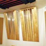
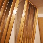
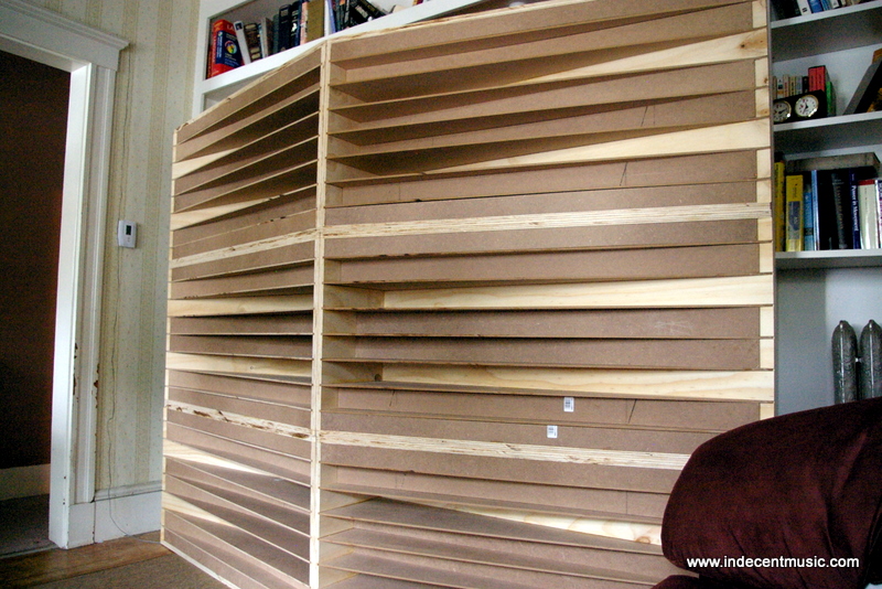
 Photos of Prototype A (left) and Prototype B (right) installed in a home studio. The left Ramp is installed permanently with molly toggle bolts and the right one is hung with the included mounting bracket.
Category: Acoustic Ramp Diffuser
We now have a way of comparing apples to apples! Using the methods described in AES-4id-2001 (r2007) “Characterisation and measurement of surface scattering uniformity,” we now have a direct comparison of the Acoustic Ramp and RPG’s QRD 734.
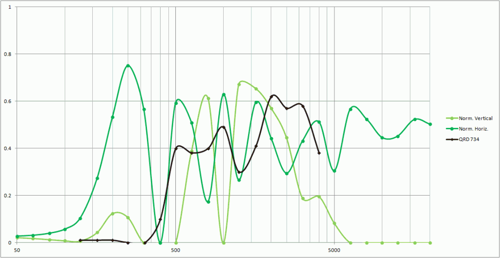
The black line is the QRD 734 and the green lines are the Acoustic Ramp™. Please note that BOTH of the green lines are happening at the same time, so you’re comparing both the green lines to the black line. As you can see the Ramp™ extends the frequency range way above and below the 734.
So we’re actually comparing a super-yummy Ginger Crisp apple to a mealy Red Delicious. Which is which?
I have tested the ramp and it does in fact work. Placing it on a stand directly behind mix positions improved bass response, removed edge from upper mids, and elongates highs so that reverb tails and quiet slaps become more apparent. It works as advertised and the change in sound from it being in place to it being removed is incredible. In my office, the biggest improvement was in the bass response. With it in place, my Tannoy Elipse 8 Actives really put out the 40hz they are rated for but when removed that enhancement was gone. There was also a lot more sizzle in the highs and the stereo field felt wider. In a lab the biggest improvement was in the midrange. There is always a murky, muddy quality to everything that you hear in there and ramp really opened it up.
-Jonathan Sage, Audio Engineer, Boston College
We have just completed Version 1.5 (2012/12/13) of the Assembly and Installation Manual for the Acoustic Ramp. This version includes the new naming convention for parts and simplified assembly instructions.
After assembling and disassembling the Ramp about 4300 times, we are reasonably confident that we have figured out the fastest and easiest way of doing it.
Please download a copy of the manual and see for yourself!
The Acoustic Ramp Assembly Manual V1.5

Acoustic testing on a budget is a daunting task. Many measurements need to be made, and sometimes several batteries of tests are required to get valid data. In the case of testing the Acoustic Ramp, I actually did an entire battery of tests that proved later to be invalid. The good news, is that I learned from my mistakes and the second battery provided good repeatable and valid data.
My test process is essentially this: Shoot a swept sine wave from a high quality studio monitor at the diffuser and record what bounces back from the diffuser with a high-quality microphone placed on the circumference of a circle with the diffuser at its center. Then I move the microphone 5 degrees along the circumference and repeat the test. Software assembles all of the data into impulse responses that when combined can create a sonogram which shows amplitude, frequency and the position of the microphone in relation to the diffuser.
Here are some photos showing the process of the testing:


Effective Diffusion Bandwidth: 300 Hz – 4 kHz (see actual data)
Effective Scattering Reflection Bandwidth: 300 Hz – 20 kHz (see actual data)
Quadratic Residue Sequence: Prime = 7
Height: 44 7/8″
Width: 24″
Depth: 12 1/4″
Weight: 40 lbs.
Reflective Material: Furniture Grade 1/2″ Pre-Finished Maple Plywood
Divider Material: Powder-coated 1/8″ Aluminum Stock
Most Effective Installation Location: Rear Wall of Rectilinear Rooms
Sonogram Directivity Results
How Does It Work?
Acoustic Diffusion is not an easy thing to test or describe. In fact in the academic acoustics world there is a big controversy about the best way to describe and measure diffusion: the Scattering Coefficient or the Diffusion Coefficient.
“You will know it works when you hear it,” is true but probably not a good explanation. I am going to avoid this whole dispute by publishing the actual data of all frequencies and amplitudes in my tests.
I did several rounds of acoustic testing on the Ramps and here is what I found:
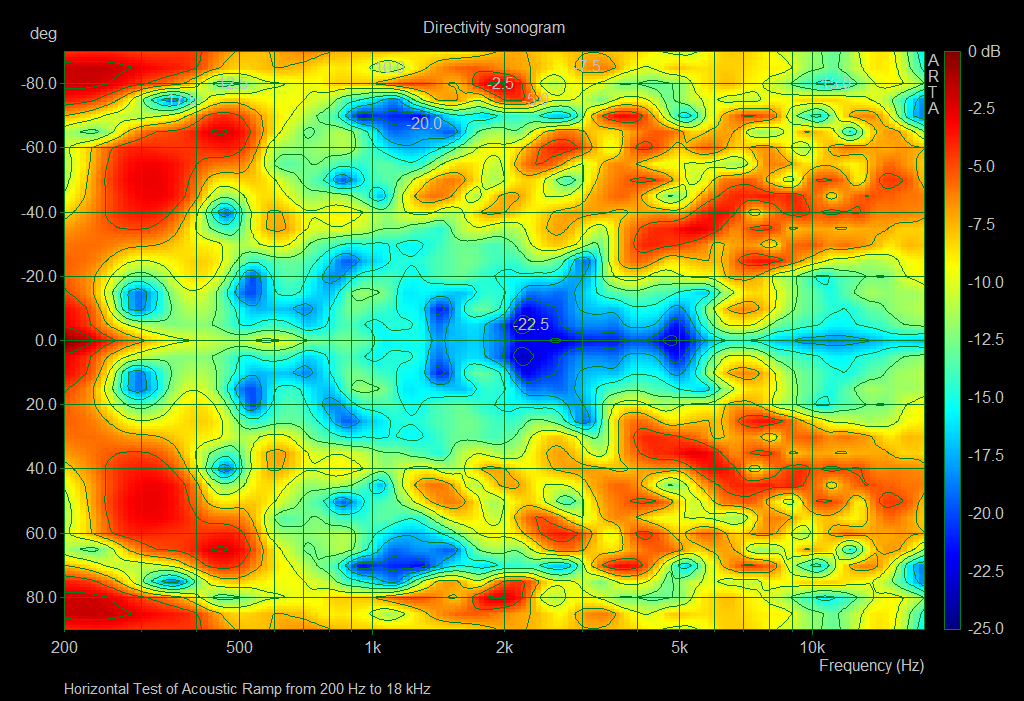
- The Acoustic Ramp scatters frequencies horizontally from about 300 Hz to about 4000 Hz (4kHz), but doesn’t do a lot below or above this bandwidth
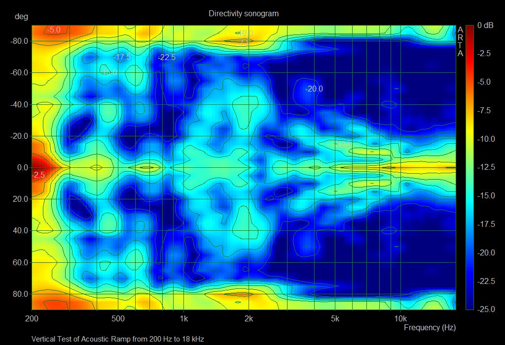
- The Acoustic Ramp scatters and reflect frequencies vertically from about 300 Hz all the way up to 20000 Hz (20kHz)
The Ramp does both of these things at the same time. So if you install the diffusers on their sides, it only changes which orientation scatters and which one reflects and scatters.
Why Do We Want To Scatter the Sound Anyway?
When sound strikes a hard flat surface most of the sound bounces off the wall as an echo. That echo can interfere with the sound that is headed towards the wall by cancelling out certain frequencies and emphasizing other frequencies. This effect is called comb-filtering. You just cannot hear sound accurately in a room that has comb-filtering problems. Scattering the sound breaks up echoes into many little tiny echoes diminishing their effect. The Ramp also reflects sound away from the sound source, further minimizing the effect of comb-filtering.
Reflections can also be controlled with absorption of course, but absorption-only treatments tend to yield rooms that sound dead and lifeless.
How Do you Read Those Diagrams?
Those diagrams are called “sonograms” and they were generated from data gathered using the software package ARTA. There will be a later post about the testing procedure, but for right now let’s focus on the diagrams.

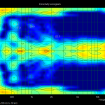
The Sonogram shows Amplitude (color), Frequency (x-axis), and Directivity (y-axis). The above diagram shows what happens when you place a loudspeaker directly in front of a flat panel. The bright yellows and reds show loud levels and the blues and dark blues show quiet levels. The stripe of brightness that goes horizontally across the center of the diagram shows that sound is bouncing right back towards the speaker. At about 500 Hz the sound is bouncing at about 30 degrees and 50 degrees off-center. And from about 300 Hz and below the reflection pattern is pretty wide.
If there is pretty good diffusion at a specific frequency the diagram will show a vertical band of similar colors. Horizontal bands of similar color means that there is an intense specular reflection at a specific angle. For instance, in the above flat reflector model, there is a very strong reflection at 0 degrees, meaning that sound hitting the reflector is bouncing straight back to the loudspeaker. If the reflector had been angled at 45°, we would expect there to be an intense band at around 45° as well.
In the horizontal test of the Acoustic Ramp™ you can see that nearly all of the energy is directed away from bounding back towards the sound source because the center of the diagram shows darker blue colors.
In the vertical test of the Ramp you can see the scattering of frequencies from about 300 Hz to around 4 kHz.
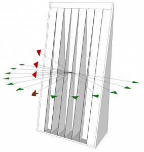
There are several reasons why the Acoustic Ramp™ works better than traditional diffusion treatments, but we’d like to focus on two major improvements in this post.
- The Ramp scatters acoustic energy horizontally while at the same time it reflects the energy over 4 different angles vertically.
- The depth of the wells of the Ramp are continuously variable leading to increased functional bandwidth.
In order to understand why these factors are important we need to discuss a few things about diffusion in general. There are two different types of diffusers that have been thoroughly tested and evaluated in the academic and in the ‘real-life’ community: the 1-Dimensional (1D) Diffuser and the 2-Dimensional (2D) Diffuser.
1-Dimensional Diffusers
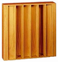
1D Diffusers are probably the most commonly used diffusers in studios and critical listening rooms and offer very predictable results. These diffusers scatter energy in a semi-circular pattern horizontally. Some examples of this type of diffuser are the following:
- RPG Inc’s QRD Diffusor (http://www.rpginc.com/products/qrd734/index.htm) This is the diffuser based most closely on Manfred Schroeder’s academic work on diffusers.
- RealTraps Diffusor (http://www.realtraps.com/diffusor.htm) This diffuser combines the QRD (Quadratic Residue Diffusion) math from Schroeder’s work with low frequency absorption.
- Primacoustic Razorblade Quadratic Diffuser (http://www.primacoustic.com/razorblade.htm) The diffuser uses a sequence of depths that doesn’t appear to be strictly a quadratic residue sequence, in that it is aperiodic and the width of the zero-depth reflectors isn’t consistent. The diffuser does offer a tremendous amount of phase-complexity and probably works very well indeed.
2-Dimensional Diffusers

2D Diffusers are most commonly referred to as Skyline diffusers after RPG Inc’s model with that name. They scatter acoustic energy in a hemispherical pattern, both horizontally and vertically. Here are some examples of 2D diffusers:
- RPG Inc’s Skyline Diffuser (http://www.rpginc.com/products/skyline/index.htm) This diffuser is based on a primitive root number sequence instead of the more commonly used quadratic residue number sequence.
- Art Diffusor Model W from Acoustics First (http://www.acousticsfirst.com/diffuser-art-diffusor-model-w.htm) This diffuser uses both the more linear 1-D architecture with various block heights of the Skyline diffuser in a unique way.
- Auralex Acoustics’ Wave Prism (http://www.auralex.com/sustain/waveprism.asp) The Wave Prism uses a grid of dividers to separate the blocks of different heights which, according to Schroeder, offers better diffusion properties.
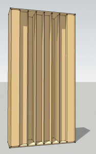
According to Schroeder’s research, both types of diffusers work on the same basic principles. The width of the wells (or the blocks) determines the upper frequency limit. The depth of the wells (or the blocks) determines the low frequency limit. The math behind this is as follows:
The wavelength (λ) of a frequency is equal to the speed of sound (c) divided by the frequency (f).
The low frequency limit of effectiveness is defined by frequency whose wavelength is four times the depth of the deepest well (or tallest block).
The high frequency limit of effectiveness is defined by the frequency whose wavelength is 2 times with width of the wells (or blocks).
Let’s use RPG Inc’s QRD 734 as an example. The wells of the 734 are roughly 9 inches deep and roughly 4 inches wide providing the following bandwidth:
Or roughly from 375 Hz to 1700 Hz.
In independent tests performed on RPG’s QRD, the actual bandwidth of diffusion extended to approximately double what Schroeder’s theory predicted. We also found in our testing that the upper limit was significantly higher than the formulas predicted.
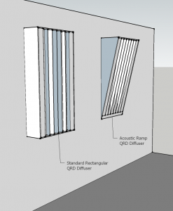
The depth of the wells is another area where the Acoustic Ramp™ has a major improvement over previous diffusive treatments. The wedge-shape of the diffuser means that the depth of the wells are continuously variable, which means that the frequency response is much wider than a typical 1-D diffuser.
Additionally, the Acoustic Ramp™ varies between a depth of 12 inches to a deep of less than a half inch. The deepest part of the diffuser is usually installed in the corner where the ceiling meets the wall, taking advantage of typically unused space in the room. The diffuser tapers as it descends the wall allowing racks, furniture and other equipment to be placed against the wall without trapping space.
The angles formed by the wedge shape of the wells allow the installer to direct reflections away from the sound source. In the most common installation, the wedge shape would direct reflections down toward the floor. In alternative installations, and array of Ramps could be used to direct reflections towards the side walls. In both of these cases, directing sound energy away from the sound sources helps to significantly reduce the effects of comb filtering.
This video slide-show depicts David Shotzberger assembling the first commercially manufactured Acoustic Ramp™ at Redco in CT. Please imagine dramatic music composed by John Williams in the background.
It takes about 20 minutes to assemble one of the Acoustic Ramps™ with only a screwdriver, and it could even be done by an intern if necessary!
